Sizes of drawings typically comply with either of two different standards ISO World Standard or ANSIASME Y141 American. Inserting Reference Geometry into Drawings.

Surface Roughness Symbol In Drawings Mechanical Engineering General Discussion Eng Tips
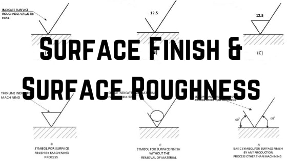
Surface Finish Indicator.
. Datum Feature Symbols. Create a spreadsheet on a 2D drawing and manually populate its content. Cannot open file 1.
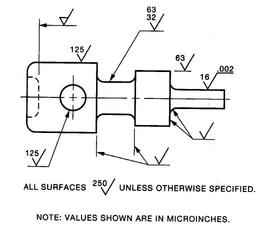
A symbol for defining the surface finish of a part. If a simple surface is called out such as a radius on a corner a height gauge can be used to trace the part as long as the gauge can stay the same distance away from the surface as rotates around the surface. Location Labels for Views.
As stated before datums can be located on points axesedges and surfaces. Supports import and export of DWG DWT and DXF file formats. Create insert and modify Bills of Materials.
Link with an Exploded. Draftsman allows the placement of Surface Finish graphical symbols and their associated parameters that comply with the ISO 13022002 International Standard for surface texture in technical product documentation. 35 Combination Drawings 33 36 Datum Planes 33 37 Draft 35 38 Flatness Straightness Waviness 35 39 Gage Dimension 35 310 Intersecting Surfaces 35 311 Mismatch and Snags 37 312 Radius 37 313 Roundness or Out of Round 39 314 Surface Roundness 39 315 Critical Characteristics 39 40 AIRFRAME DIVISION IDENTIFICATION OF PARTS 40 41.
Engineering drawings could be readily doubled or halved in size. Relation to Other GDT Symbols. I dont want that but dont know how to turn it off so that.
Using the Symbol Library. They are shown enclosed in a box. Symbols Used In GDT Callouts.
The metric drawing sizes correspond to international paper sizesThese developed further refinements in the second half of the twentieth century when photocopying became cheap. Create fully detailed drawings of parts and assemblies with dimensions datums surface finish and weld symbols geometric tolerances notes tables balloons callouts sheets and fully configurable drawing properties. Im doing as-builts of a historic structure and the walls are very slightly out of alignment with the x-y axes.
Here is how different types of features are called out on engineering drawings. Ordinate chamfer dimensions Datums Surface Finish Feature Control Frame Tolerance Weldments. Whenever Im drawing something thats nearly but not quite horizontal or vertical Revit forces it to be aligned to x-y axes.
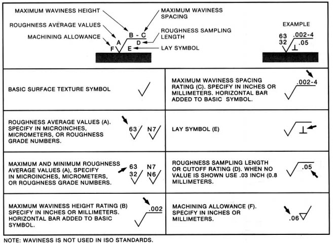
The standard specifies the rules for the indication of surface texture in drawings based on special. Develops the only product design platform that combines 3D CAD PDM collaboration and analytics tools in the cloud. The symbol must be placed on or with one single.
Notation is Important on Drawings. The difference between them is that. It is important though that they is called out correctly on the drawing to control the right type of feature.
Basic dimensions represent a theoretically perfect feature or size. Profile of a surface is the 3D version of profile of a line. There are many variations of the surface texture symbol but most often it is used with a microinch or micrometer value callout that specifies the roughness of a surface.
Convert any view into a fully shaded view similar to the look of a 3D model. CFD Not Responding 1. Cant edit element 1.
Complete Surface Finish Chart Symbols Roughness Conversion Tables

Surface Finish Wikipedia
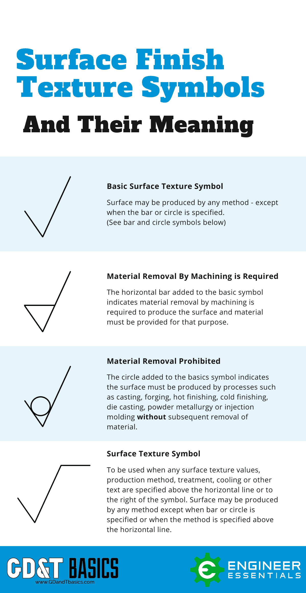
The Basics Of Surface Finish Gd T Basics
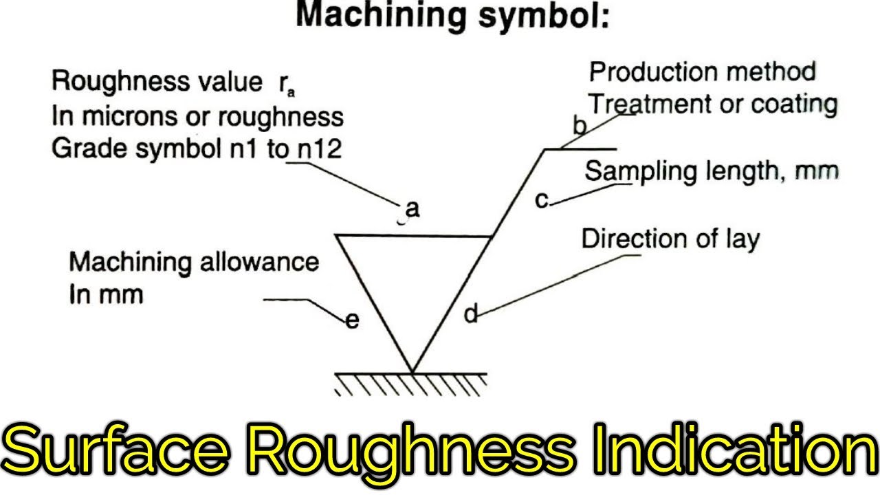
Surface Roughness Indication Symbols Surface Roughness Symbol Indication In Hindi Youtube
Iso Surface Roughness Symbols Terminology
Dimensions Surface Finish Roy Mech
Complete Surface Finish Chart Symbols Roughness Conversion Tables
Surface Finish Surface Roughness It S Indications Symbols
0 comments
Post a Comment